Custom Steel Gear Shafts for Speed Reducers | CNC Machining to Drawing in China
Custom steel gear shafts for speed reducers, made to your drawings in China. CNC machining, gear cutting, heat treatment and inspection for OEM orders.
Custom Steel Gear Shafts for Speed Reducers | CNC Machining to Drawing in China
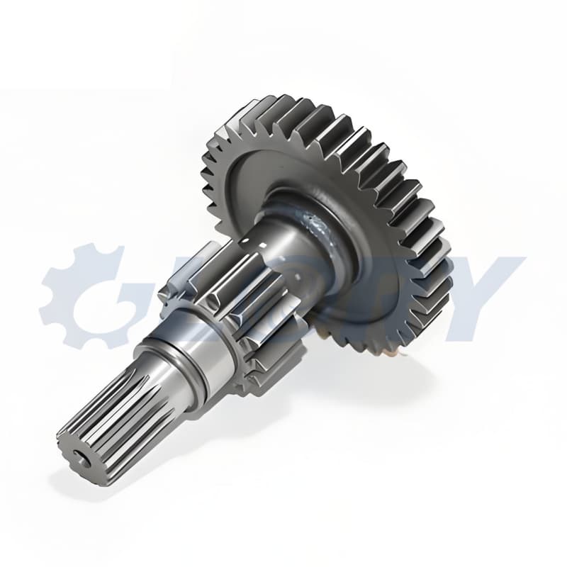
A steel gear shaft combines gear teeth and shaft features in one component, making the relationship between tooth geometry, bearing journals and mounting surfaces essential to gearbox assembly. For equipment manufacturers and industrial buyers, sourcing these parts requires careful coordination of material selection, machining, heat treatment and final inspection.
We supply custom steel gear shafts for speed reducers according to customer drawings and technical requirements. As a China-based foreign trade company specializing in custom machined parts, we coordinate production and export supply for prototypes, replacement components and repeat orders. Our service covers drawing review, material sourcing, CNC machining, gear cutting, specified heat treatment and inspection.
From a single prototype to scheduled production batches, each project is reviewed around the actual gear geometry, shaft structure and operating requirements.
Our OEM gear shaft service supports spur and helical gear designs, including integral pinion shafts and stepped shafts with multiple functional features. Gear teeth, bearing seats, seal journals, splines, keyways and threads are manufactured to the approved drawing.
| Product configuration | Features that can be customized | Typical application |
|---|---|---|
| Spur pinion shaft | Straight gear teeth, stepped diameters, bearing journals and shaft ends | Parallel-shaft speed reducers |
| Helical pinion shaft | Helix angle, helix hand, tooth width, bearing seats and locating shoulders | Helical gearboxes and geared drives |
| Intermediate gear shaft | Integral gear section, additional gear seats, shoulders and locating features | Multistage reduction gearboxes |
| Splined gear shaft | Integral gear teeth combined with external splines | Gearbox and coupling connections |
| Keyed gear shaft | Gear section, keyways, retaining grooves and end threads | Industrial transmission assemblies |
| Special stepped gear shaft | Non-standard lengths, diameters, relief grooves and mounting details | Custom machinery and replacement projects |
Steel selection should follow the gearbox design, required core strength, tooth surface condition and component size. The examples below illustrate different material and heat treatment approaches; the final grade and delivery condition are agreed before production.
| Steel grade | Typical heat treatment approach | Purpose in a gear shaft design |
|---|---|---|
| 1045 carbon steel | Quenching and tempering; induction hardening of selected areas when specified | General shaft applications with strength and local wear requirements appropriate to the grade and section size. |
| 4140 alloy steel | Quenching and tempering; optional induction hardening or nitriding to an approved specification | Transmission shafts requiring greater strength and hardenability than plain medium-carbon steel. |
| 8620 alloy steel | Carburizing followed by hardening and tempering | Gear shafts requiring a wear-resistant case with a comparatively tough core. |
Other drawing-specified steel grades can be reviewed for sourcing and processing. Any proposed material substitution is submitted for customer approval before production.
Heat treatment requirements should identify the treated areas, surface hardness, core hardness where applicable, effective case depth and any areas that must remain unhardened. These details help coordinate gear cutting, machining allowances and final finishing.
Custom gearbox gear shaft machining involves more than turning the outside profile. The production route must also account for tool access, gear cutting clearance, workholding, heat treatment distortion and the relationship between the gear teeth and bearing journals.
We coordinate CNC turning and milling with suitable gear cutting and finishing operations. Hobbing or shaping is selected according to the tooth geometry and available clearance. Cylindrical grinding and gear tooth finishing are included where required by the drawing and confirmed during technical review.
| Production stage | Main work | Key control point |
|---|---|---|
| Drawing and process review | Review shaft geometry, gear data, material and inspection requirements | Resolve missing information before production |
| Blank preparation | Prepare bar stock or a specified forged blank | Confirm material condition and machining allowance |
| Rough machining | Turn main diameters, shoulders, faces and reference features | Establish consistent machining datums |
| Gear and feature machining | Cut gear teeth and machine specified splines, keyways, holes and threads | Control feature relationships and tool clearance |
| Heat treatment | Apply the approved treatment to the specified areas | Control hardness, case depth where applicable and distortion |
| Final finishing and inspection | Finish critical journals and tooth surfaces as required, then inspect | Verify the finished component against agreed requirements |
The sequence is adapted to the material and final condition. For hardened gear shafts, finishing allowances are planned before heat treatment so that critical dimensions can be achieved while retaining the required hardened layer.
A gear shaft must fit its bearings and mating components while maintaining the specified relationship between its gear teeth and rotational datums. Our inspection planning therefore considers both shaft geometry and gear characteristics.
Dimensional checks can include CMM measurement, micrometers, gauges and runout checks, selected for the feature being inspected. Gear profile, helix and pitch requirements are assessed using suitable gear measurement methods agreed for the project.
| Inspection item | Typical checks | Relevance to assembly |
|---|---|---|
| Bearing journals and mounting diameters | Diameter, fit tolerance, roundness and surface finish as specified | Bearing and component fit |
| Gear geometry | Tooth count, tooth thickness, profile, pitch and helix where applicable | Compatibility with the mating gear |
| Runout and alignment | Gear and journal runout relative to drawing datums | Rotational alignment |
| Shoulders and axial dimensions | Shoulder spacing, face position and perpendicularity | Axial location of bearings and mounted parts |
| Splines, keyways and threads | Dimensions, fit and position using suitable gauges or measurement | Connection with mating components |
| Heat-treated areas | Hardness and case depth where specified | Verification of the required material condition |
| Surface condition | Burrs, damaged edges, grinding marks and cleanliness | Handling and assembly readiness |
Inspection scope, sampling frequency and reporting requirements are agreed before production. Critical dimensions can be identified for 100% inspection when requested. Gear accuracy, shaft tolerances and surface finish are quoted against the specific drawing.
Custom steel reducer gear shafts are used in conveyor drives, packaging machinery, material handling equipment, industrial mixers, agricultural machinery and other mechanical transmission systems. We support both new equipment projects and replacement parts made to approved technical data.
For repeat orders, maintaining the approved drawing revision, material condition and inspection requirements helps support consistent supply. Order quantities can start from one piece, subject to review of the component and required processes. Lead time is confirmed according to material availability, tooling, heat treatment, finishing requirements and quantity.
Finished parts can be supplied with suitable rust protection and protective packing for gear teeth, precision journals and threaded ends. Part identification and inspection records can be arranged to match the customer’s purchasing requirements.
For a quotation, please provide a dimensioned 2D drawing and, where available, a 3D model. Gear information should include tooth count, module or diametral pitch, pressure angle, tooth width and the required accuracy. For helical gears, specify the helix angle and hand, and identify whether module and pressure angle are defined in the normal or transverse system.
The drawing should also identify profile shift or tooth modifications where applicable, tooth thickness or inspection dimensions, shaft fits, datums, runout limits, surface finish, material grade and heat treatment requirements. Please include order quantity, expected repeat demand, inspection documents and the required delivery date.
Our custom steel gear shaft supply service in China brings machining, gear cutting, heat treatment and inspection into one coordinated order. Send your approved drawings for a project-specific quotation covering prototypes, small batches or ongoing OEM gearbox component supply.
About Us
 We provide custom machined parts, 5-axis linkage CNC machining, and the design, production, and assembly of machinery and equipment.