Custom Single-Start Worms and Worm Wheels Machined to Drawings in China
Custom single-start worms and worm wheels machined to your drawings in China. Steel worm shafts, bronze wheels, and matched pairs for OEM equipment.
Custom Single-Start Worms and Worm Wheels Machined to Drawings in China
Custom single-start worms and worm wheels provide a practical solution for equipment that requires compact speed reduction, controlled rotary motion, and specific mounting dimensions. We supply custom worm shafts, mating worm wheels, and complete worm gear pairs manufactured according to customer drawings for gearboxes, positioning devices, adjustment mechanisms, and industrial machinery.
As a China-based foreign trade company specializing in custom machined components, we coordinate drawing review, material sourcing, machining, heat treatment, inspection, and export delivery. Our service supports overseas OEMs, equipment builders, and industrial buyers sourcing non-standard worm gear components for prototypes, small batches, and repeat production.
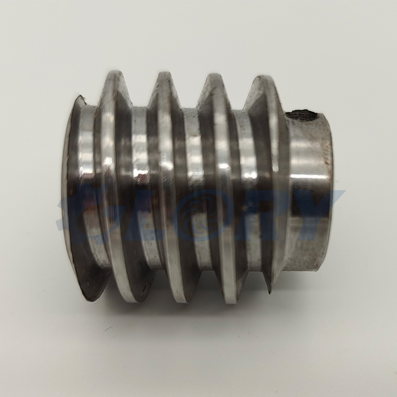
A single-start worm, also called a single-thread worm, has one continuous helical thread. Each complete revolution of the worm advances its mating wheel by one tooth. The reduction ratio equals the number of worm wheel teeth divided by the number of worm starts. For example, a single-start worm paired with a 40-tooth worm wheel produces a 40:1 reduction ratio.
The required operating performance depends on the complete gear pair and its installation. A single-start design alone does not guarantee self-locking; backdriving behavior depends on lead angle, friction, lubrication, and operating conditions.
Production is based on the approved drawings and agreed technical requirements. The following features can be specified for a custom worm and worm wheel project.
| Item | Customization Details |
|---|---|
| Supply scope | Individual worm shafts, individual worm wheels, or complete mating pairs |
| Worm configuration | Single-start worm with an integral shaft or separate worm body |
| Thread direction | Right-hand or left-hand design with compatible mating wheel geometry |
| Gear geometry | Specified module or diametral pitch, pressure angle, worm profile, and lead |
| Reduction ratio | Determined by the single-start worm and specified wheel tooth count |
| Assembly dimensions | Center distance, shaft arrangement, wheel position, and mounting references |
| Worm shaft features | Bearing journals, shoulders, keyways, flats, grooves, holes, and end threads |
| Worm wheel features | Custom bore, hub, keyway, mounting holes, and overall dimensions |
| Material and condition | Drawing-specified grades, heat treatment, hardness, and surface condition |
| Acceptance requirements | Dimensional tolerances, tooth accuracy, backlash, and inspection scope |
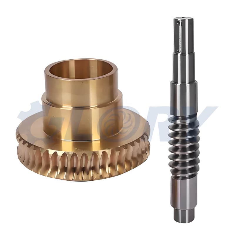
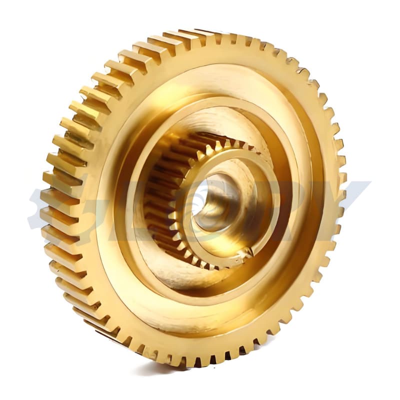
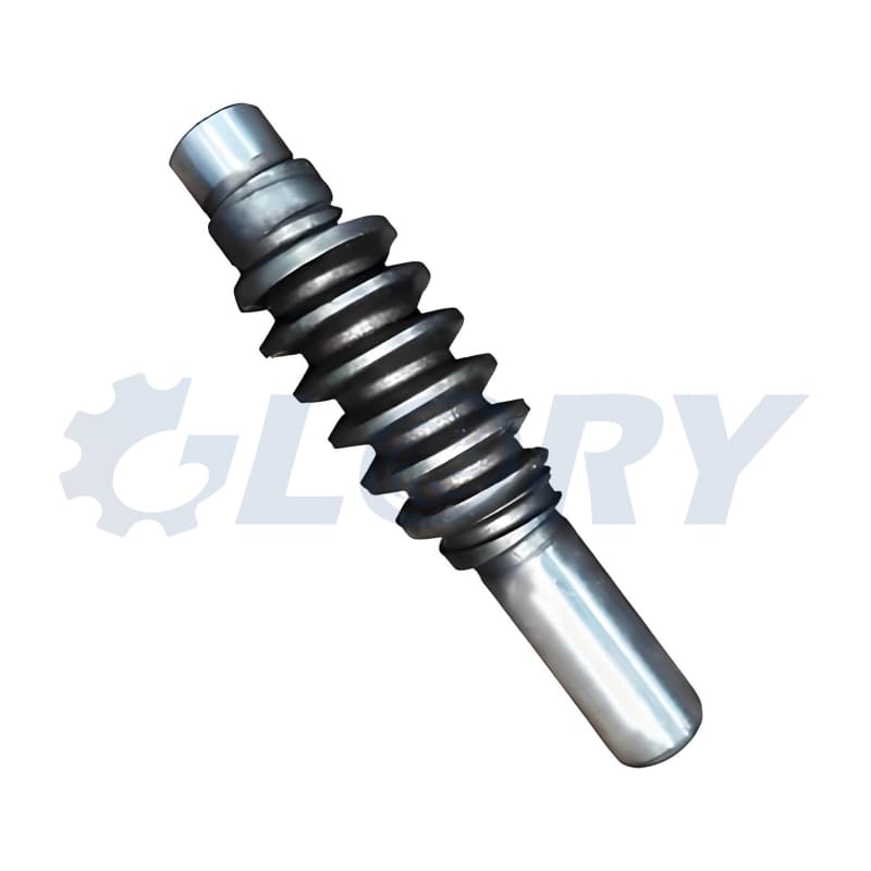
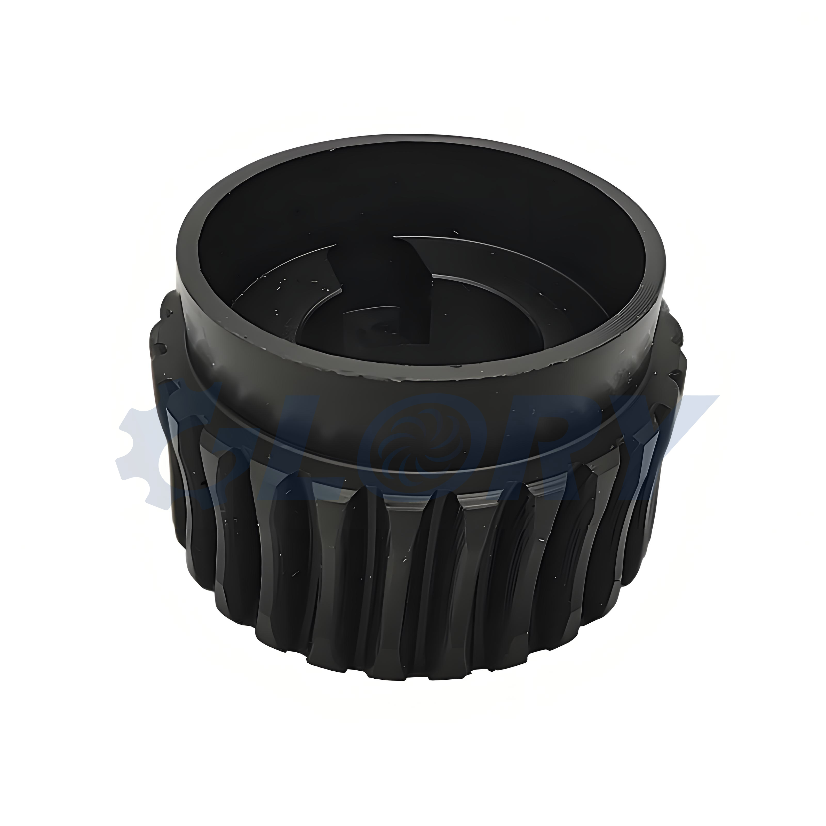
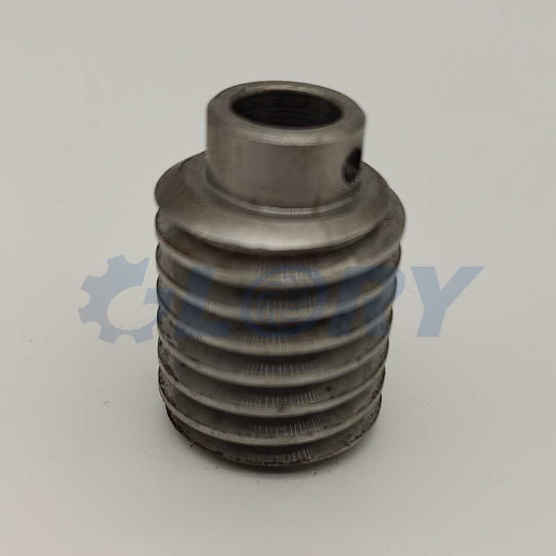
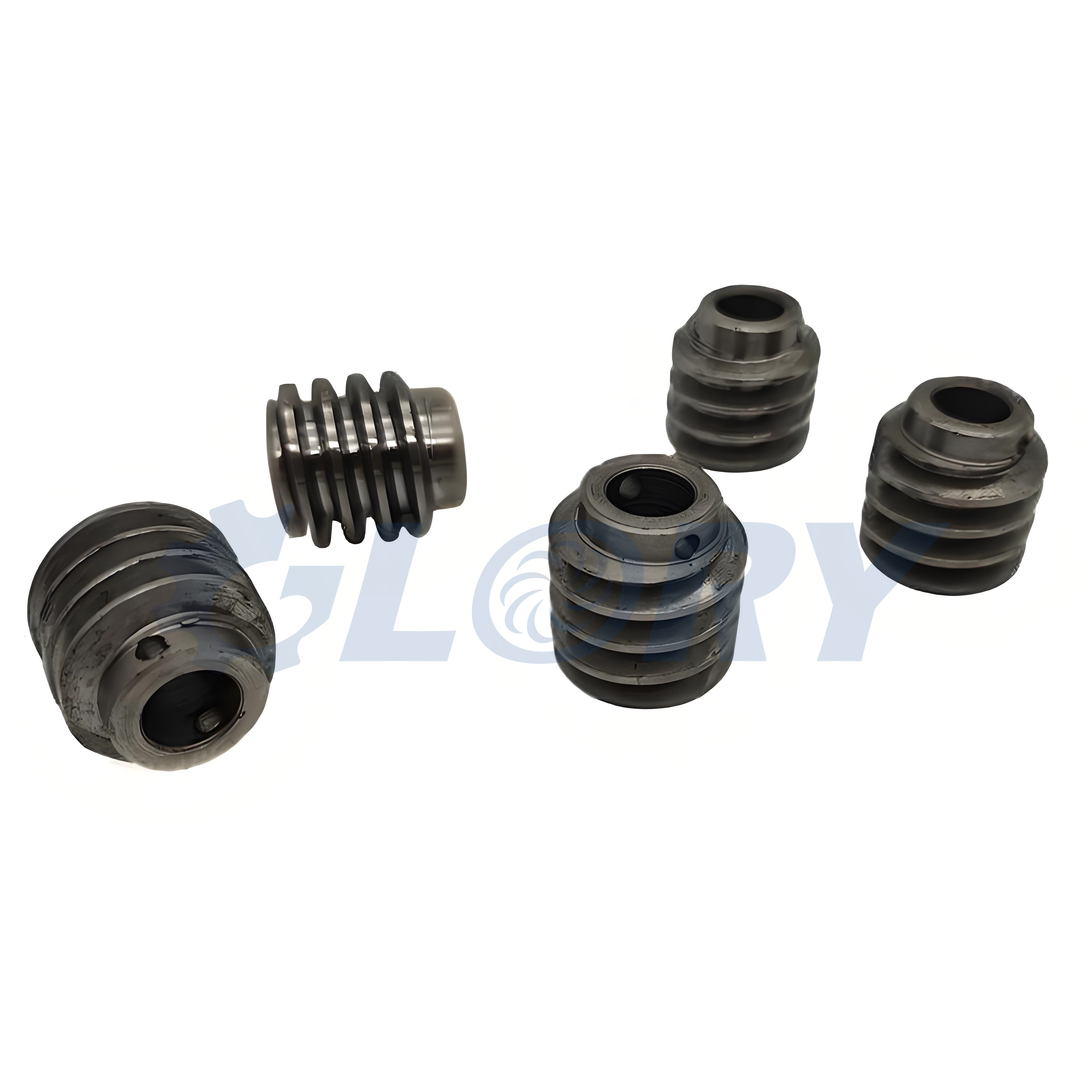
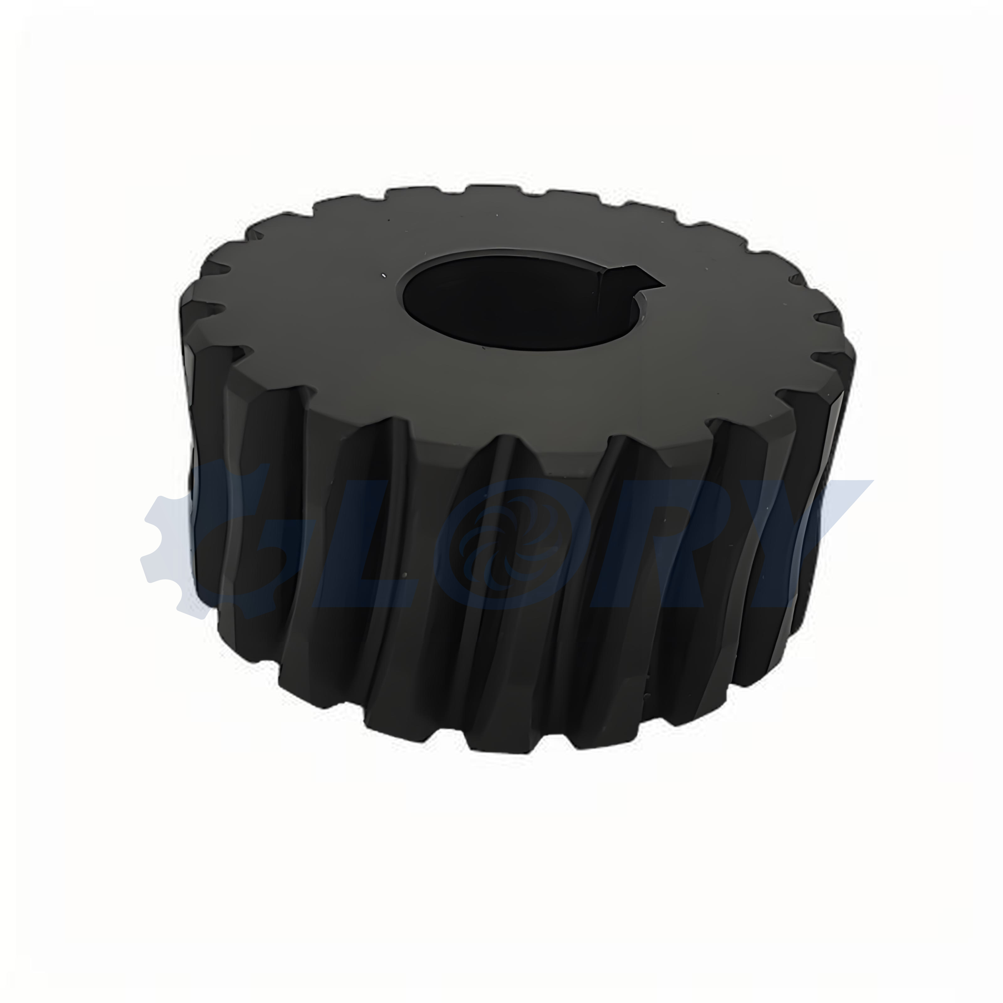
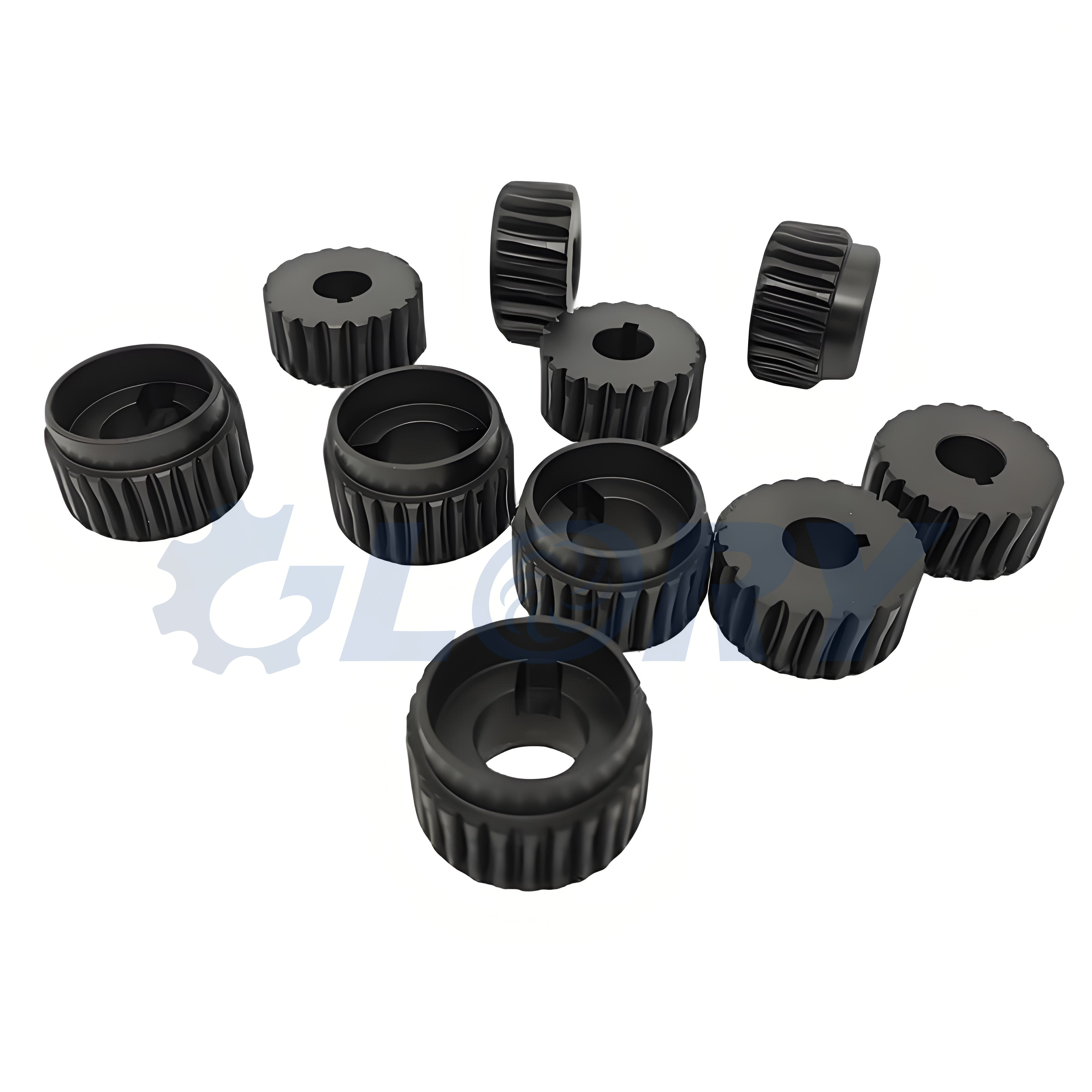
Correct matching is essential when ordering a worm and worm wheel. Matching the nominal module and tooth count alone is insufficient. The module system, pressure angle, worm profile, lead angle, thread direction, and operating center distance must also be compatible. A custom worm wheel must have the tooth geometry required to mesh with its intended worm.
For replacement components, drawings of both mating parts or reliable data for the existing assembly help establish compatibility. Ordering the pair together allows its geometry and agreed meshing requirements to be reviewed as one project.
Material selection is based on load, speed, duty cycle, lubrication, wear requirements, and the customer’s specification. Steel worms combined with bronze worm wheels are a common arrangement. Other combinations can be reviewed for the intended application.
| Component | Material Options for Review | Specification Considerations |
|---|---|---|
| General-purpose worm shaft | Medium-carbon steel, such as C45 or AISI 1045 | Define the exact grade, supply condition, and any required hardening |
| Alloy steel worm shaft | Grades such as 40Cr or AISI 4140 | Select heat treatment and finished hardness to suit the shaft and tooth requirements |
| Case-hardened worm | Case-hardening grades such as 20CrMnTi or AISI 8620 | Specify case depth, surface hardness, core requirements, and finishing allowance |
| Bronze worm wheel | Drawing-specified tin bronze or phosphor bronze | Confirm the alloy, blank form, and suitability for the intended operating conditions |
| Brass worm wheel | Drawing-specified brass | Review suitability for the particular load and speed; do not assume interchangeability with bronze |
The grades listed above are separate material options, not declarations of equivalence. The exact material designation and delivery condition are confirmed before production. Any proposed substitution is submitted for customer approval.
The manufacturing route is selected according to component geometry, material condition, tooth profile, and required accuracy. Worm shaft production may combine blank preparation, CNC turning, thread machining, milling of secondary features, heat treatment, and finish grinding where specified. Bearing journals and mounting surfaces are controlled relative to the drawing datums.
Worm wheel production may include machining the blank, bore, hub, and faces, followed by hobbing or another suitable tooth-cutting process. The tooling and cutting geometry must suit the mating worm. Keyways, mounting holes, and other secondary features are completed according to the drawing and process plan.
Heat treatment is selected for the specified steel rather than applied as a universal process. Depending on the grade and design, requirements may include quenching and tempering, induction hardening, or carburizing followed by hardening and tempering. Allowance for distortion and subsequent finishing is considered when planning critical dimensions.
Surface finishing is also reviewed by function. Tooth flanks, bearing seats, seal-running surfaces, and non-working areas can require different finishes. Any coating or treatment affecting a fitted or meshing surface must be included in the dimensional requirements.
Inspection focuses on both individual component dimensions and the agreed requirements of the mating pair.
| Inspection Area | Typical Features to Check |
|---|---|
| Worm shaft dimensions | Journal diameters, overall length, shoulders, grooves, keyways, and end features |
| Worm wheel dimensions | Bore size, hub dimensions, face width, keyway, and mounting-hole positions |
| Geometric accuracy | Runout, perpendicularity, and relationships between drawing datums |
| Tooth geometry | Specified worm lead and profile, wheel tooth count, and applicable tooth accuracy requirements |
| Heat treatment and finish | Specified hardness, case depth where applicable, surface roughness, and edge condition |
| Pair meshing | Contact pattern, backlash, and rotation at the agreed center distance when included in the inspection scope |
CMM inspection and conventional measuring instruments can be used for suitable dimensional and geometric features. Gear-specific measurements and meshing checks are defined separately according to the requested accuracy and acceptance criteria. Inspection records and 100% inspection of agreed critical features can be arranged.
Custom single-start worm gear components can be incorporated into a range of industrial assemblies, subject to the application’s design requirements.
| Application | Typical Function |
|---|---|
| Industrial speed reducers | Compact reduction between the input and output shafts |
| Rotary tables and positioning devices | Controlled angular movement |
| Packaging machinery | Adjustment and positioning of machine elements |
| Conveyor equipment | Speed reduction or adjustment within the drive assembly |
| Valve operating mechanisms | Rotary reduction for controlled valve actuation |
| General machinery | Custom transmission components for new builds and replacement projects |
Our custom worm gear machining service in China brings machining, secondary processing, inspection, and order coordination into one purchasing workflow. Drawing revisions, material requirements, critical dimensions, and delivery expectations are confirmed for each order. Prototype quantities and repeat batches can be planned around the project’s tooling and production requirements.
For a quotation, provide the latest 2D drawings and available 3D models for the worm and worm wheel, together with the required quantity, material grades, heat treatment, and delivery target. Include the tooth count, module system, pressure angle, worm profile, thread direction, center distance, and any backlash or contact-pattern requirements. For application review, input speed, output torque, duty cycle, and lubrication details are also useful.
Whether you need a custom single-start worm shaft, a bronze worm wheel, or a complete worm gear pair machined to drawings, we support sourcing from China with clearly defined specifications, coordinated production, and inspection matched to your order.
About Us
 We provide custom machined parts, 5-axis linkage CNC machining, and the design, production, and assembly of machinery and equipment.