
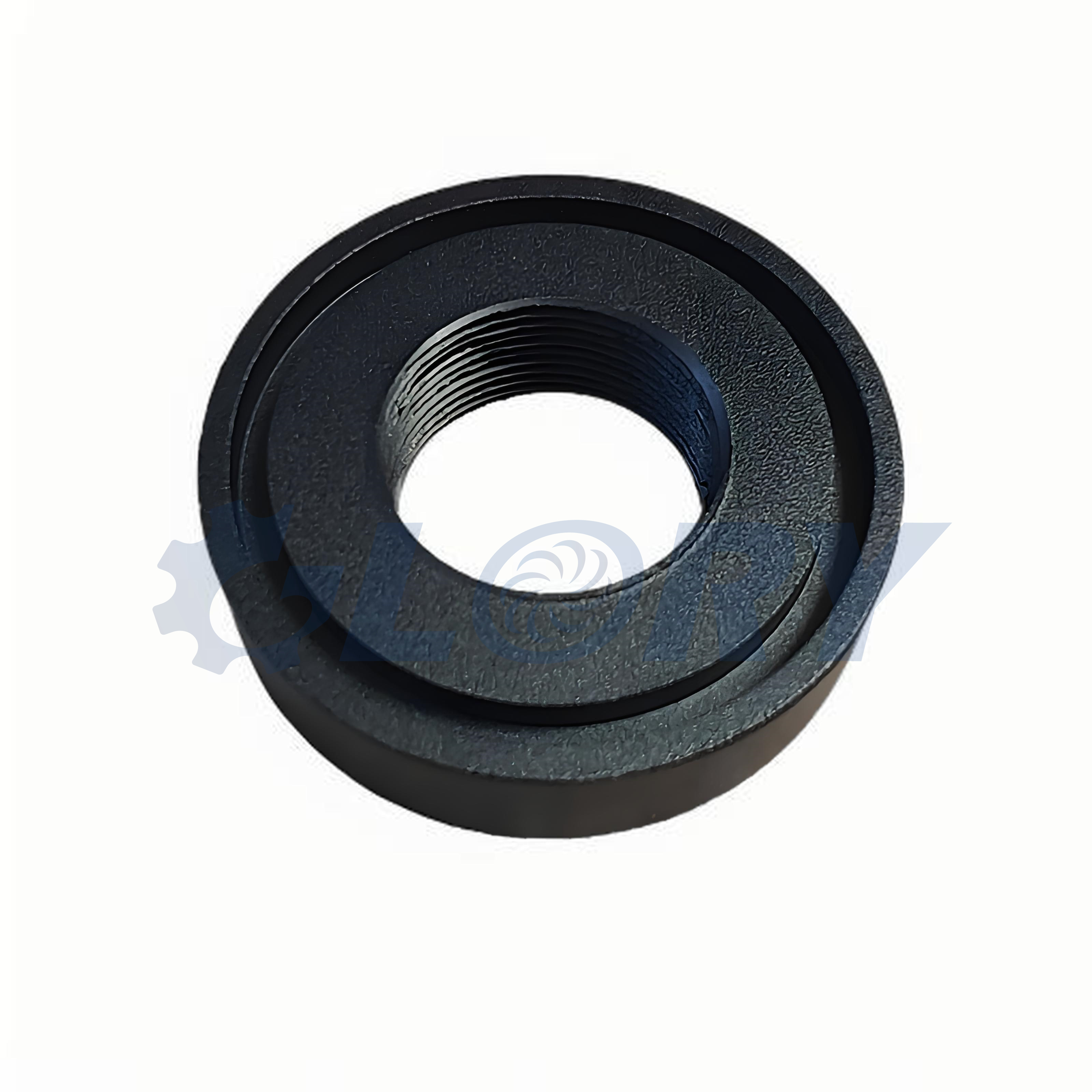
Custom CNC Machined 6061 Aluminum Optical Parts | Precision Optomechanical Components
Lens barrels, mirror mounts, housings, spacers and adapters. Tolerance to ±0.005 mm, matte black anodize for stray-light control, prototypes to production.
Qingdao Glory manufactures CNC machined 6061 aluminum optical parts for OEMs, integrators and research teams building laser systems, imaging modules, scientific instruments, machine-vision cells and photonic equipment. Every component is built to order from your drawing — there is no standard catalog, because optical hardware is almost never truly “standard.”
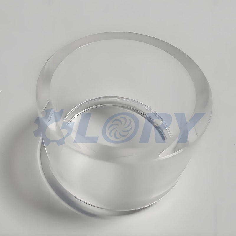
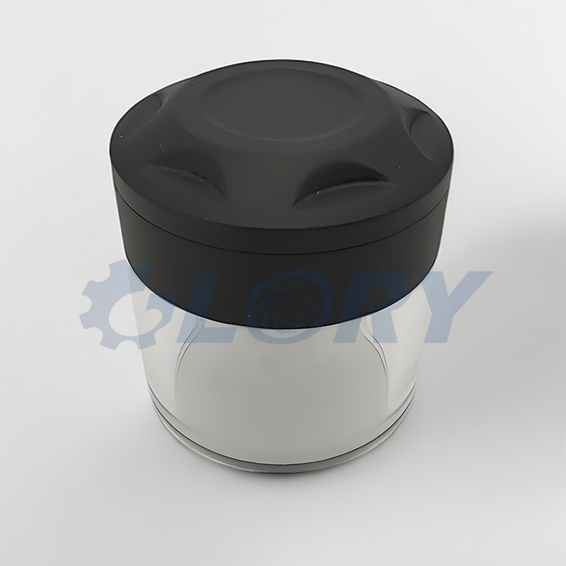
We turn and mill 6061 (most often in the -T6 temper) into lens barrels, lens cells, mirror and kinematic mounts, filter holders, adapter rings, laser and camera housings, optical baseplates and the small hardware that holds an optical axis where the design says it should be. Bores are sized for the actual lens seating diameter, interface threads can be cut to metric, unified or optical-standard profiles (SM1/SM2, cage-system spacing), and critical surfaces can be supplied matte-black anodized to suppress stray light and internal reflection.
Whether you need 5 revised prototypes for an R&D bench, a 200-piece pilot batch, or recurring production orders with fixed fixturing and lot traceability, the work runs through the same documented process: drawing review → DFM feedback → first-article inspection → batch production → CMM/gauging verification → controlled finishing and packing.
Why 6061 Aluminum Is the Default Choice for Optical Hardware
Designers specify 6061 for optomechanical parts because it sits at a useful balance point: stiff enough to hold alignment, light enough for moving stages, easy to machine to fine finishes, and predictable under anodizing. Typical values for 6061-T6:
| Property | Typical value (6061-T6) | What it means for an optical part |
|---|---|---|
| Ultimate tensile strength | ~310 MPa (45 ksi) | Handles normal clamping and mounting loads without deformation |
| Yield strength | ~276 MPa (40 ksi) | Retains datum geometry under screw preload |
| Elastic modulus | 68.9 GPa | Good rigidity for barrels, mounts and plates |
| Hardness | ~95 HB | Hears fine tool marks; resists handling damage |
| Density | 2.70 g/cm³ | Roughly one-third the weight of steel — matters on gimbals and stages |
| Thermal conductivity | ≈167 W/m·K | Conducts heat away from laser diodes and sensors |
| Elongation | 10–12% | Tolerates assembly stresses without brittle failure |
| Machinability | Good to excellent | High feeds, clean bore surfaces, stable thread cutting |
| Anodizing response | Excellent | Uniform matte black finish for glare control |
6061 also welds and anodizes more consistently than most alternatives, costs less than 7075, and is far stronger than 6063 where threads and seating faces carry load. If your application actually calls for 7075 (higher strength), 5052 (formed covers), 6082 (European drawings), brass or stainless steel (retaining rings, adjustment screws), we machine those as well — tell us the service environment and we will confirm the material choice instead of silently substituting.
Material is sourced from certified mills and every production lot ships with a material test certificate on request; chemical composition and temper are fully traceable.
Range of CNC Machined 6061 Aluminum Optical Parts We Build
Most jobs fall into one of the families below, but we are not limited to them — any geometry you can dimension on a drawing can be quoted.
- Lens barrels and lens cells — single- and multi-element barrels with precision seating bores, shoulder steps, retaining-ring threads and centration features; internal bore surfaces machined for minimum reflection after black anodize.
- Retaining rings and lock rings — internal/external threaded rings with spanner holes or slots, in 6061 or stainless as specified.
- Mirror mounts, kinematic mounts and tip/tilt frames — spring-loaded and adjuster-driven mounts where datum flatness and hole pattern directly set beam angle.
- Prism, beamsplitter and wave-plate holders — pocketed seats with controlled clearances, clamp ledges and strain-free mounting surfaces.
- Filter holders, iris mounts and aperture parts — thin-walled rings and stepped adapters with burr-free edges.
- Adapter rings and spacers — C-mount, T-mount, SM1 (1.035″-40), SM2 (2.035″-40), M25–M45 series, custom male/female thread conversions, precision shim spacers in graded thicknesses.
- Laser module and diode housings — collimator tubes, focus barrels, heatsink bodies with fins or press-fit bores.
- Camera and sensor housings — CCD/CMOS mounting brackets, enclosed bodies with gasket grooves, tripod and dovetail interfaces.
- Optical baseplates, breadboards and pedestals — grid-tapped plates (M4/M6, 1″ or 25 mm spacing), angle brackets, posts, post holders and mounting feet.
- LiDAR, endoscope, microscope and telescope components — scanner housings, turret parts, focus tubes and structural rings produced to customer prints.
Machining Capabilities and Tolerance Control
Optical parts fail on geometry, not just on dimensions — a bore that measures correctly but is out of round will still decenter a lens, and a mount face that is not square to the bore will tilt the beam. Our process controls both.
| Capability | Standard we hold |
|---|---|
| Processes | 3/4-axis CNC milling, CNC turning with live tooling (turn-mill in one clamping), 5-axis coordination for complex geometry, surface/cylindrical grinding and honing on request |
| General machining tolerance | ISO 2768-m / ±0.02 mm where drawing does not specify |
| Precision dimensional tolerance | ±0.005 mm standard on critical features; ±0.002 mm on selected bores and seats when geometry allows |
| Bore roundness / cylindricity | Down to 0.003–0.005 mm on turned lens seats |
| Concentricity / coaxiality | 0.005–0.01 mm between bore and thread/OD datums |
| Flatness, parallelism, perpendicularity | To 0.005 mm on mounting datums and mirror faces |
| As-machined surface roughness | Ra 1.6–3.2 µm; Ra 0.8 µm on turned seating surfaces |
| Honed / ground internal surfaces | Ra 0.2–0.4 µm; Ra 0.1 µm class on optical-path surfaces where specified |
| Thread forms | Metric, unified, SM1/SM2 optical threads, C/T-mount, custom pitches — all checked with ring/plug gauges |
| Work envelope | Turned parts from ~2 mm to 300 mm diameter; milled plates and housings to roughly 500 × 400 × 300 mm; larger on review |
| Minimum practical wall | ~0.5 mm, subject to material and fixturing review |
We do not quote a “universal” tolerance number on the homepage and then miss it on the floor. Achievable precision depends on feature size, depth-to-diameter ratio, material stock and how the part is clamped, so every drawing gets a feature-by-feature review, and any tolerance we judge risky is flagged before cutting metal, with a suggested relaxation or alternative datum scheme.
Surface Treatment — Built for Optical Use
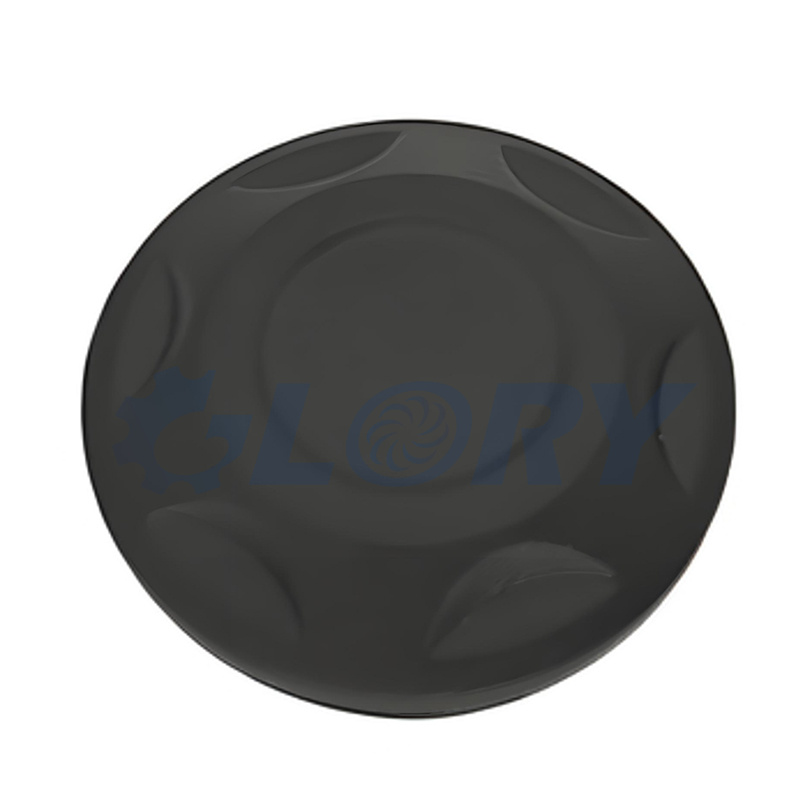
The default finish for CNC machined 6061 aluminum optical parts is matte black anodize, because a shiny internal wall scatters light straight onto the sensor or focal plane. Options include:
- Type II sulfuric anodize, matte black (per MIL-A-8625 / equivalent) — the standard for barrels, housings and mounts; low reflectance, durable, clean-cut edges.
- Type III hardcoat anodize — thicker, harder layer for wear surfaces such as rotating barrels and sliding focus tubes; available black or natural.
- Clear / colored anodize — red, blue, gold or custom coding for identification rings.
- Bead blasting / satin finishing before coating for uniform, non-directional appearance.
- Chemical conversion (chromate) and bare degreased finishes where electrical grounding or later bonding is required.
- Laser engraving of part numbers, revision letters, serial numbers and alignment marks.
A detail many low-cost shops miss: anodizing adds a layer. We machine critical bores and threads to a calculated pre-anodize dimension with a fixed coating allowance (typically 0.005–0.012 mm per side for Type II, more for hardcoat), so the finished bore — not the pre-coat bore — lands on your nominal dimension. Threads, press-fit diameters and mating faces can be masked where coating is not wanted; masking requirements are called out during our drawing review rather than assumed.
Quality Control and Documentation
- In-process checks after first operation and at every setup change, with recorded results.
- First Article Inspection (FAI) report with measured values against every ballooned dimension before batch release.
- CMM, digital height gauge, micrometers and bore gauges, pin/thread gauges, optical comparator and surface-roughness tester; calibration on a maintained schedule.
- 100% inspection on critical features, AQL-based sampling on non-critical dimensions, or customer-defined inspection plans — your choice.
- Material mill certificates, coating thickness measurement, RoHS compliance statements and third-party (e.g., SGS) reports arranged on request.
- Non-conforming parts are quarantined, never mixed into a shipment; if a deviation is ever proposed, you receive the data and approve it in writing first.
Typical Applications
- Laser systems: marking, welding, measurement and medical laser modules
- Imaging and machine vision: industrial cameras, smart-vision cells, line-scan housings
- Life-science and analytical instruments: microscopy, spectroscopy, cytometry, endoscopy
- Defense, aerospace and UAV payloads: stabilized gimbals, electro-optical turrets, LiDAR scanners
- Research and university labs: custom breadboard hardware and one-off experimental setups
- Photonics and telecom: collimators, fiber coupling mounts, optical switch enclosures
Why Buy Your CNC Machined 6061 Aluminum Optical Parts From Us
- True custom, non-standard focus. We do not resell catalog mounts. Your print, your tolerances, your marking and your packaging — including neutral or customer-branded packing.
- Engineering feedback before you pay for it. Every inquiry receives a DFM review: sharp internal corners, impossible-to-machine pockets, under-toleranced non-critical features and coating-stock issues are raised up front, with practical fixes.
- Prototype-friendly and production-stable. One-off and 5-piece prototype runs are normal for us; once a design is frozen, fixturing, tooling and inspection plans are retained so repeat orders match the first batch.
- Optics-specific finishing discipline. Pre-anodize dimension compensation, controlled matte black surfaces, masked threads and burr-free internal edges are handled as standard, not as extras discovered late.
- Predictable lead times and communication. A named contact answers email within one working day; you receive progress photos, inspection data and tracking without chasing. Typical lead time: 7–15 working days for prototypes, 15–30 days for production batches, depending on quantity and finishing.
- Export experience. Regular shipments to North America, Europe, Russia, South Asia and Africa; we work to EXW/FOB/DDP terms as needed and support customer-specified forwarders.
How to Order / Custom Manufacturing Workflow
- Send files: STEP, IGES, X_T, DWG/DXF or PDF (2D drawing with tolerances and finish callouts is always preferred over a model alone).
- Tell us quantity, target delivery date, material/temper, surface treatment and any inspection or certification requirements.
- We return a quotation with DFM notes within 24 hours on most parts.
- Sample/prototype made and inspected; FAI report and photos sent for approval.
- Production, in-process and final QC, finishing, packing and door-to-door shipping arrangement.
NDA support is available — your drawings, assemblies and project information are never shown to other buyers or used in any public portfolio without written permission.
Frequently Asked Questions
Q: Are these truly CNC machined 6061 aluminum optical parts, or do you also offer other materials? 6061-T6 is our most common optical grade because of its strength-to-weight balance and anodizing result, but we also machine 6063, 6082, 7075, 5052, brass, copper, titanium and 303/304/316 stainless for mixed-material assemblies.
Q: What tolerance can you actually hold on a lens barrel bore? On turned seating bores we routinely hold ±0.005 mm, and ±0.002 mm on selected features when diameter, wall thickness and fixturing permit. We confirm the achievable value per feature during drawing review instead of promising one number for every geometry.
Q: Why is black anodize used inside optical parts, and does it change my dimensions? Matte black anodize absorbs stray light and prevents internal reflection that degrades contrast. The coating adds thickness, so critical bores and threads are machined to a pre-anodize allowance; finished dimensions are verified after coating, which is what your assembly will actually see.
Q: Can you cut SM1/SM2 and cage-system threads and hole patterns? Yes — 1.035″-40 (SM1), 2.035″-40 (SM2), C-mount, T-mount, metric fine threads and 30 mm/60 mm cage-system spacing are routine, verified with matching gauges.
Q: What is your MOQ? There is no fixed MOQ for custom work. One-piece prototypes are accepted; unit pricing improves at 50/100/500-piece breaks, and recurring orders can be scheduled against a forecast.
Q: Do you provide inspection documents with the shipment? Yes: FAI reports, dimensional records, material certificates, coating-thickness checks and, when required, independent third-party reports can be supplied. State the documentation package with your RFQ so it is built into the plan.
Q: What surface roughness can you reach on internal optical-path surfaces? Standard turning reaches Ra 0.8–1.6 µm inside bores; honing brings seating and optical-path surfaces to Ra 0.2–0.4 µm, with Ra 0.1 µm-class finishing available on specified features.
Q: How fast can I get a quote and samples? Most quotes go out within 24 hours of receiving a complete drawing. Prototype parts typically ship in 7–15 working days, including black anodize.
Send Us Your Drawing
Upload your STEP/PDF file with quantity and finishing requirements, or contact us. Our engineering team will come back with a manufacturable, costed proposal for your CNC machined 6061 aluminum optical parts.
About Us
 We provide custom machined parts, 5-axis linkage CNC machining, and the design, production, and assembly of machinery and equipment.