
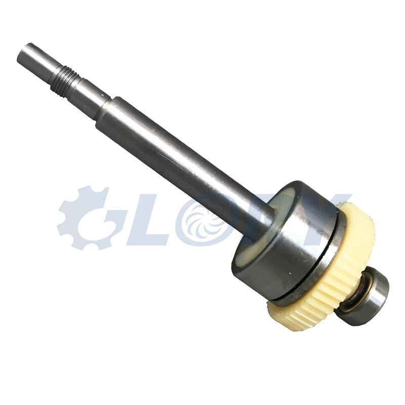
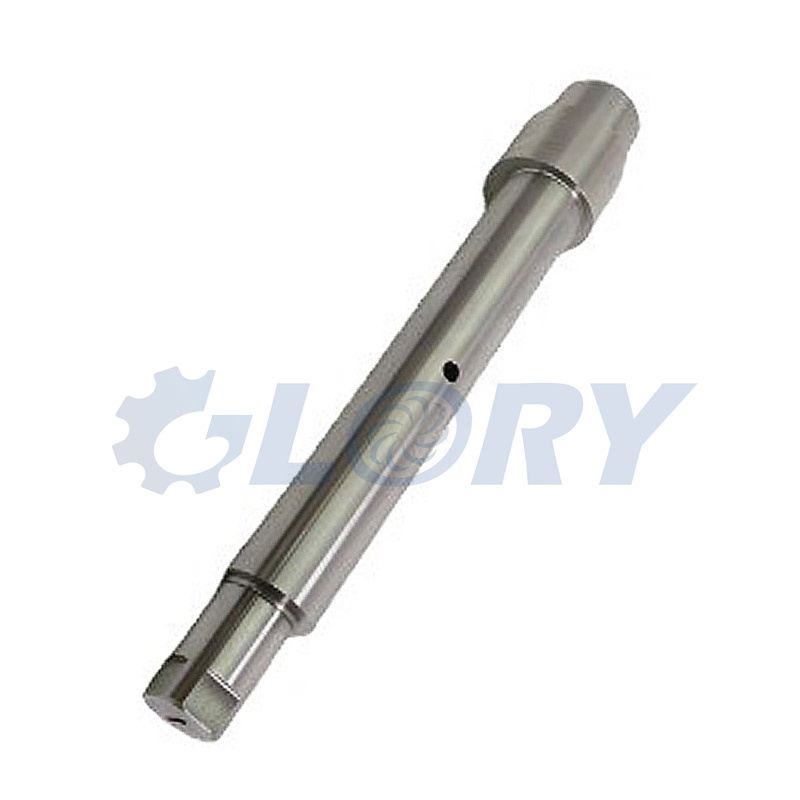
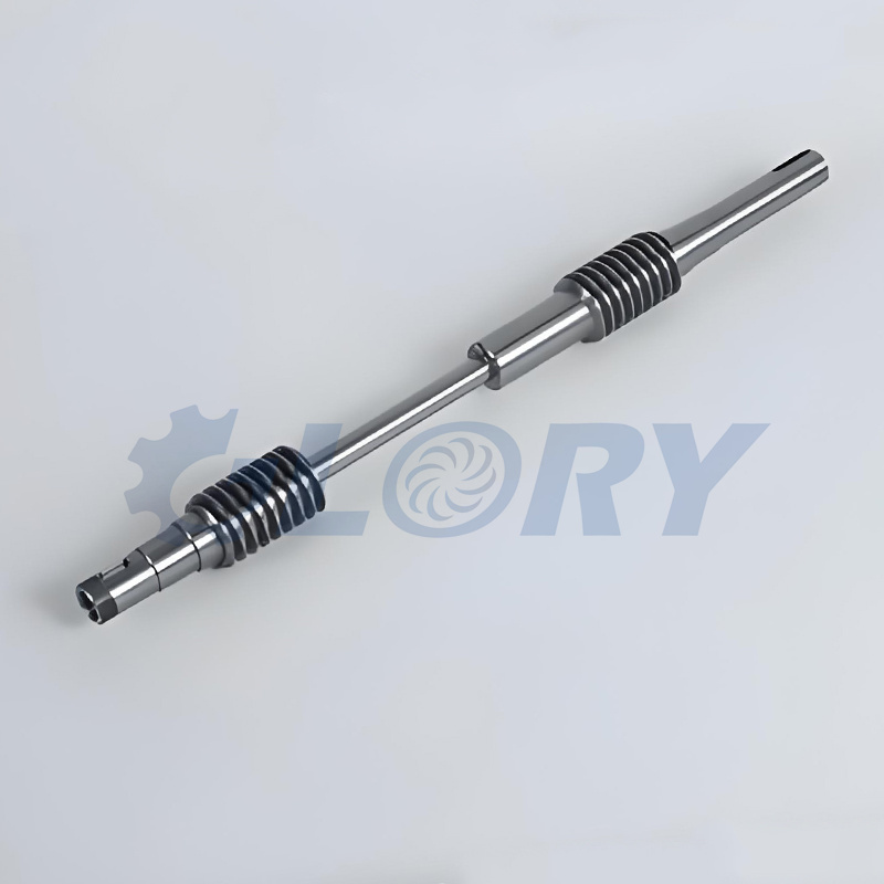
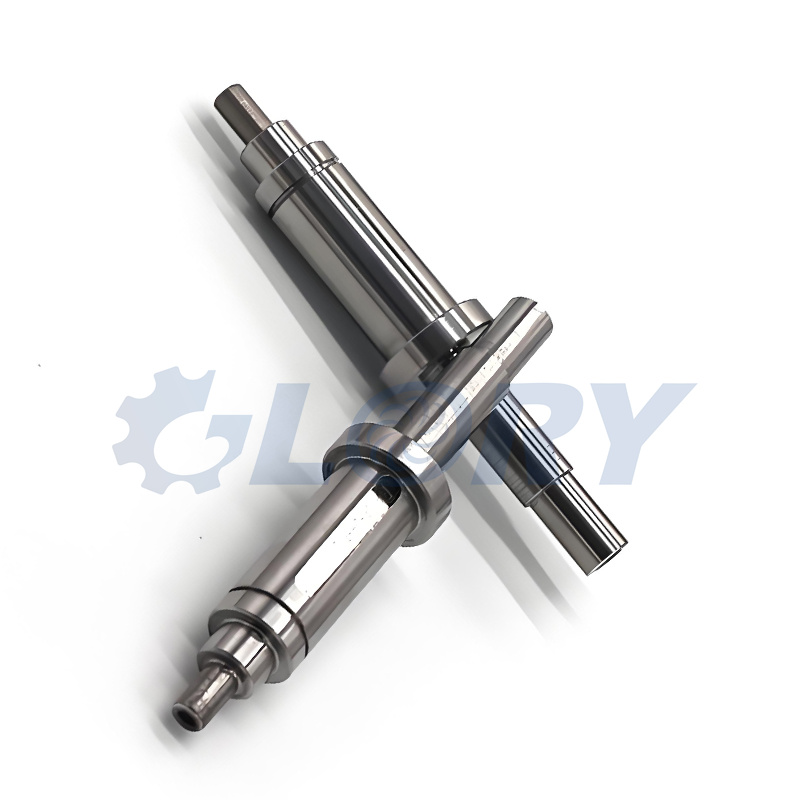
The stepped shaft is one of the most widely used core components in mechanical transmission systems. It is mainly used to support transmission parts such as gears and belt pulleys and transmit torque and motion. It is widely applied in machine tools, automobiles, construction machinery and other equipment. The machining accuracy and surface quality of shaft parts directly determine the transmission accuracy, operational stability and service life of mechanical equipment. Taking a typical 45# steel stepped shaft part as the research object, this paper conducts a comprehensive processability analysis based on its structural characteristics and technical requirements, formulates a complete machining procedure, and analyzes key machining difficulties and quality control points, providing reliable process references for batch production of similar shaft parts.
1. Part Drawing and Overall Technical Requirements
1.1 Detailed Drawing Parameters
This process analysis is based on a standard three-section stepped shaft engineering drawing, which is a classic component commonly used in mechanical course design and workshop training. It features a simple structure, complete parameters and standardized tolerances, and can be fully matched with the subsequent machining process.
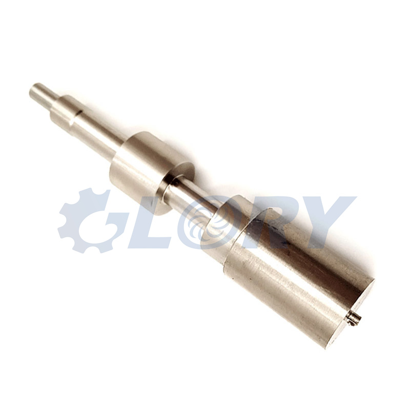
- Overall Dimensions: Total shaft length = 180 mm; maximum outer circle diameter = Φ40 mm; middle matching journal diameter = Φ35 mm; right-end shaft diameter = Φ30 mm. The part is a three-section rotary stepped structure without threads, keyways or holes.
- Dimensional Tolerances: Left shaft segment Φ40 mm (IT9, tolerance: 0/-0.062 mm), length = 60 mm; middle matching journal Φ35 mm (IT7, tolerance: 0/-0.025 mm), length = 80 mm; right shaft segment Φ30 mm (IT9, tolerance: 0/-0.052 mm), length = 40 mm. The tolerance of all axial lengths is ±0.05 mm.
- Structural Features: C2 chamfer at both end faces of the shaft; C1 chamfer at all shaft shoulder transitions; no relief grooves; shaft shoulder fillet R0.5 mm.
- Surface Roughness: The outer circle of the Φ35 mm matching journal Ra ≤ 1.6 μm; outer circles of non-matching segments and shaft shoulder end faces Ra ≤ 6.3 μm; center holes and chamfered surfaces Ra ≤ 12.5 μm.
- Geometric Tolerances: Based on the common axis of the two-end center holes, the cylindricity of the Φ35 mm journal ≤ 0.02 mm; overall coaxiality of all shaft segments ≤ 0.02 mm; perpendicularity of shaft shoulder end faces to the shaft axis ≤ 0.03 mm.
- General Drawing Specifications: Unscheduled dimensional tolerances comply with GB/T 1804-M; unscheduled geometric tolerances comply with GB/T 1184-K; finished parts shall be burr-free, scratch-free and collision-free.
1.2 Material Selection and Properties
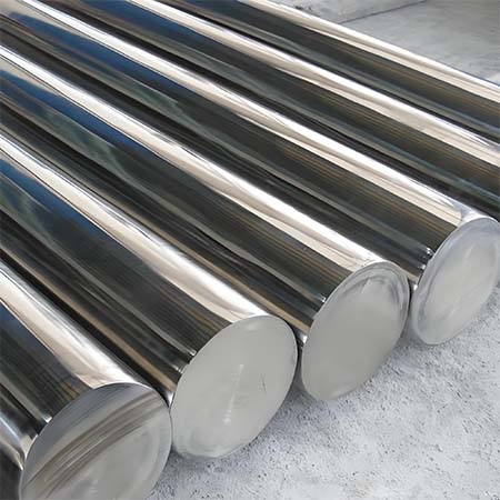
The part adopts 45# high-quality carbon structural steel. After quenching and high-temperature tempering (normalizing treatment), it possesses excellent comprehensive mechanical properties with good strength, toughness and plasticity. It has superior cutting performance and no quenching cracking tendency, which fully meets the load requirements of conventional mechanical transmission shafts. The blank adopts hot-rolled round steel with a diameter of Φ45 mm, which requires no forging and is suitable for small and medium batch production.
1.3 Heat Treatment Requirements
Overall quenching and tempering treatment is required, with hardness controlled within 220~250HBW. The treatment eliminates residual blank stress and cutting stress, refines the metallographic structure, improves the dimensional stability and comprehensive mechanical properties of the part, and prevents bending and torsional deformation during equipment operation.
2. Comprehensive Machining Processability Analysis
2.1 Structural Processability Analysis
The stepped shaft is a typical rotary part with simple and regular structures. All machining surfaces are standard cylindrical surfaces and planes, without complex special-shaped surfaces, deep grooves or narrow slits. The diameter transition of each shaft segment is gentle, and the shaft shoulder height is reasonable, allowing smooth tool feeding and retracting without machining interference. The end chamfer design effectively removes burrs, facilitates assembly, and prevents edge chipping during processing. The overall structure is highly adaptable to conventional horizontal lathe machining with excellent process feasibility.
2.2 Precision Processability Analysis
The core precision requirements are concentrated on the dimensional accuracy, cylindricity and coaxiality of the Φ35 mm matching journal. The IT7-level precision can be stably achieved through the combined process of rough turning, semi-finish turning and finish turning without grinding, which effectively reduces production costs. Geometric tolerances are guaranteed by one-time clamping and sectional machining to avoid positioning errors caused by repeated clamping. The surface roughness of Ra 1.6 μm can be realized by finish turning with optimized cutting parameters and tool selection, showing good precision processability.
2.3 Material Processability Analysis
Under annealed and tempered conditions, 45# steel has low cutting resistance, regular chip formation and low tool wear, which is suitable for machining with cemented carbide turning tools. The hot-rolled round steel blank has uniform machining allowance without pores, slag inclusions and other casting defects, effectively avoiding chipping and vibration lines during processing. In addition, the heat treatment process of 45# steel is mature with minimal deformation after tempering, ensuring high dimensional stability of finished parts.
2.4 Key Machining Difficulties
The main machining difficulties lie in coaxiality control of multi-section shafts and surface quality control in finish turning. Segmented turning is prone to clamping errors and machine tool motion errors, resulting in coaxiality out-of-tolerance. Unreasonable cutting speed and feed rate in finish turning will cause tool marks and vibration lines, failing surface roughness requirements. In addition, micro deformation will occur after heat treatment, so a reasonable finishing allowance must be reserved for deformation compensation.
3. Machining Process Scheme Design
3.1 Production Type and Equipment Selection
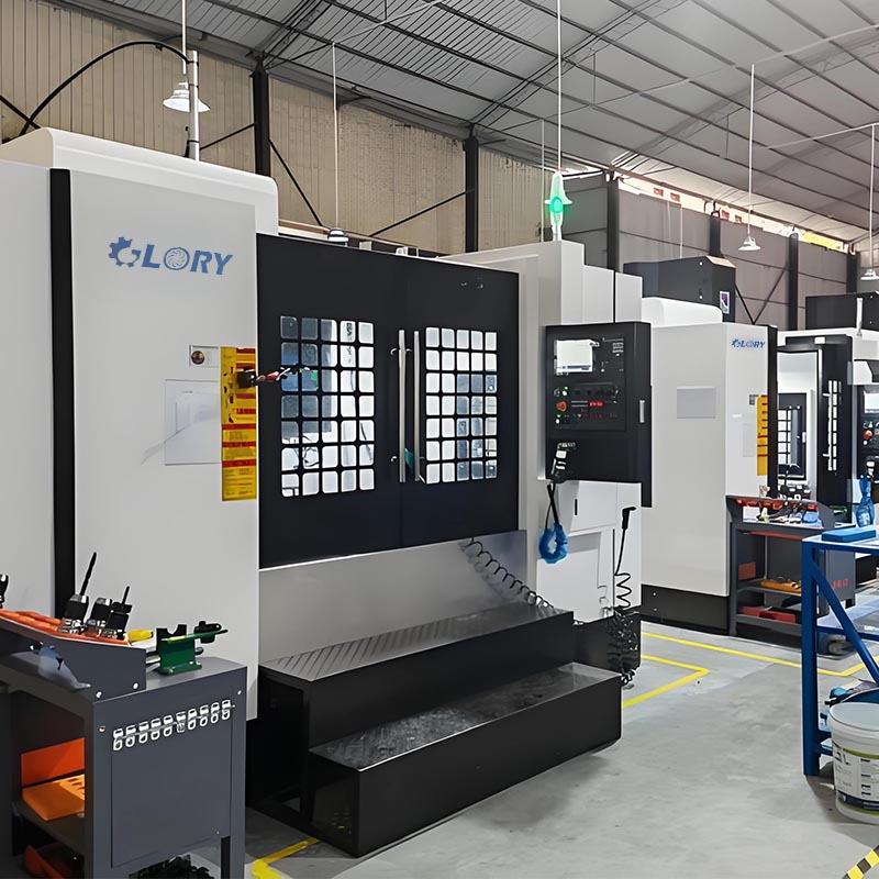
This process is designed for small and medium batch production. The core processing equipment adopts a CA6140 conventional horizontal lathe to complete all turning procedures. Auxiliary equipment includes a metal sawing machine (blank cutting), heat treatment furnace (tempering), measuring tools such as vernier calipers, micrometers and dial indicators, and chamfering machines. All equipment is versatile and suitable for conventional workshop production conditions.
3.2 Positioning Datum Selection
Following the principles of datum unification and datum coincidence: the outer circular surface of the blank is used as the rough datum for preliminary positioning in rough machining; double-top center holes are adopted as the precise datum in finish machining. The center hole positioning features high precision and stable clamping, which effectively ensures the coaxiality and geometric accuracy of all shaft segments, realizes datum unification in multiple processes, and avoids datum conversion errors.
3.3 Overall Process Flow
In accordance with the machining principles of “rough first, finish later; main first, secondary later; plane first, circle later; datum first”, the process flow is formulated as follows: blank cutting → blank pretreatment → center hole drilling → rough turning of all shaft segments → tempering heat treatment → center hole grinding → semi-finish turning → finish turning forming → chamfering and deburring → precision inspection → finished product warehousing. Rough machining removes most allowance rapidly, heat treatment eliminates machining stress, and finish turning guarantees final dimensional accuracy and surface quality.
4. Detailed Machining Procedures and Parameter Settings
4.1 Procedure 1: Blank Cutting
A metal sawing machine is used to cut Φ45 mm hot-rolled 45# steel round steel. Based on the total shaft length of 180 mm, a machining allowance of 3~5 mm is reserved, and the blank size is Φ45 mm × 185 mm. Burrs at both ends of the blank are removed after cutting to prevent inaccurate positioning and equipment scratching in subsequent clamping.
4.2 Procedure 2: Blank Pretreatment
Visual inspection is carried out to eliminate unqualified blanks with cracks, corrosion and pits. The straightness of the blank is corrected to avoid coaxiality out-of-tolerance caused by blank bending and ensure uniform machining allowance of the whole part.
4.3 Procedure 3: Drilling Two-End Center Holes (Datum Machining)
The blank outer circle is clamped by a three-jaw chuck and aligned, and a center drill is used to machine A-type center holes at both ends. The center holes are matched with the lathe top in angle and depth with smooth and burr-free inner walls, serving as the unified precision positioning datum for all subsequent finishing processes.
4.4 Procedure 4: Rough Turning of All Shaft Segments
The workpiece is clamped with double tops and machined with a cemented carbide external turning tool. The core purpose of rough turning is to remove redundant allowance rapidly. The radial finishing allowance per side is 1.5~2 mm, and the axial allowance is 1 mm. Cutting parameters: cutting speed v=60~80 m/min, feed rate f=0.2~0.3 mm/r, cutting depth ap=1~1.5 mm. Only the outline of the three-section stepped shaft is formed without strict precision control, and the blank oxide layer is completely removed.
4.5 Procedure 5: Overall Tempering Heat Treatment
After rough machining, the part is quenched at 830 ℃ and tempered at 550 ℃ with appropriate holding time to ensure uniform hardness of 220~250HBW. The heat treatment eliminates blank residual stress and cutting stress, refines the metallographic structure, improves the strength and toughness of the part, and prevents structural deformation and failure in service. The part is cooled naturally after heat treatment, and surface oxide scales are cleaned.
4.6 Procedure 6: Center Hole Grinding
Micro deformation and oxidation of center holes will occur after tempering. The two-end center holes are ground with a grinding top to remove oxide layers and correct circular runout errors, ensuring close fitting between center holes and lathe tops, restoring datum precision, and providing a precise foundation for finish turning coaxiality control.
4.7 Procedure 7: Semi-Finish Turning
Double-top positioning is adopted continuously with a special finish turning cemented carbide tool. The machining allowance is further reduced, with a radial finishing allowance of 0.3~0.5 mm per side. Optimized cutting parameters: cutting speed v=100~120 m/min, feed rate f=0.15~0.2 mm/r. Semi-finish turning eliminates residual shape errors from rough machining, trims shaft shoulder end faces to ensure flatness and perpendicularity to the shaft axis, and reduces cutting load for finish turning.
4.8 Procedure 8: Finish Turning Forming (Core Procedure)
Finish turning is the key procedure to guarantee final precision, adopting high-rigidity cutting mode with high speed and low feed. Cutting parameters: cutting speed v=120~150 m/min, feed rate f=0.08~0.12 mm/r, cutting depth ap=0.15~0.25 mm. Machining is strictly carried out according to drawing dimensions for Φ30 mm, Φ35 mm and Φ40 mm shaft segments to meet IT7 and IT9 tolerance standards. Cutting fluid is fully supplied throughout the process to reduce cutting temperature, inhibit tool wear and machining vibration, and ensure the surface roughness of the matching journal reaches Ra ≤ 1.6 μm.
4.9 Procedure 9: Chamfering and Deburring
A chamfering tool is used to machine C2 chamfers at both ends of the shaft and C1 chamfers at all shaft shoulder transitions. Machining burrs and sharp edges are completely removed to avoid scratching matching parts during assembly, eliminate stress concentration risks and improve the overall appearance quality of the part.
4.10 Procedure 10: NC Finish Turning G-Code Programming
This paper adopts the GSK980TDb CNC lathe system to compile dedicated finishing programs for the three-section stepped shaft. The program fully matches the above finish turning parameters and drawing precision requirements, which can be directly applied to CNC lathe practical processing. This program is only for finish turning forming (outer circle, end face and chamfer), and rough turning still adopts conventional lathe processing to ensure high precision and dimensional consistency of batch parts.
4.10.1 Programming Preconditions
- Workpiece Coordinate System: G54, the center of the workpiece right end face is set as X0, Z0 origin;
- Machining Tool: T0202 finish turning external tool (coated cemented carbide tool);
- Cutting Parameters: Spindle speed S1200 r/min, feed rate F0.1 mm/r, consistent with finish turning process parameters;
- Machining Scope: Finish turning of three-section outer circles, shaft shoulders, end faces and C1/C2 chamfers;
- Safety Settings: The tool returns to a safe position before processing, and cutting fluid is turned on throughout the process.
4.10.2 Complete NC G-Code Program
O0001 ;Program Number
G99 G21 G40 ;Feed per revolution / Metric unit / Cancel tool radius compensation
T0202 ;Call No.2 finish turning tool and load tool compensation
S1200 M03 ;Spindle forward rotation 1200r/min
M08 ;Turn on cutting fluid
G00 X50.0 Z5.0 ;Rapid positioning to safe starting point

;Finish turning right-end Φ30 shaft & C2 end chamfer
G00 X28.0 Z2.0
G01 Z0 F0.1
X30.0 Z-2.0 ;Right-end C2 chamfer forming
Z-40.0 ;Finish turning Φ30 outer circle

;Finish turning middle Φ35 matching journal & C1 shoulder chamfer
X33.0 Z-41.0
X35.0 Z-42.0 ;Shaft shoulder C1 chamfer
Z-122.0 ;Finish turning key precision journal Φ35

;Finish turning left-end Φ40 shaft & C1 shoulder chamfer
X38.0 Z-123.0
X40.0 Z-124.0 ;Shaft shoulder C1 chamfer
Z-180.0 ;Finish turning total shaft length

;Tool retraction and program end
G00 X50.0 ;X-axis safe retraction
Z5.0 ;Z-axis safe return
M09 ;Turn off cutting fluid
M05 ;Stop spindle rotation
G40 X100.0 Z100.0 ;Cancel compensation and return to tool change point
M30 ;Program end and reset
4.10.3 Program Process Matching Explanation
The G-code program accurately matches the part drawing dimensions and machining process standards, precisely forming the three-section shaft diameters and all chamfer specifications. The high-speed and low-feed finishing mode stably guarantees the IT7 dimensional accuracy and Ra1.6 μm surface quality of the key Φ35 mm matching journal. The processing sequence follows the mechanical processing principle of “right to left, end face first then outer circle, chamfer first then fine turning”, without idle stroke and processing interference. It maintains consistent quality control standards with manual finishing and is suitable for high-precision batch production.
4.11 Procedure 11: Precision Inspection and Warehousing
Precision micrometers are used to detect dimensional tolerances of each shaft segment; dial indicators are adopted to test cylindricity, coaxiality and perpendicularity; a roughness meter is used to verify surface roughness. All technical indicators are checked one by one against drawing requirements. Qualified parts are cleaned of oil stains and iron filings, treated with rust prevention and warehoused. Unqualified parts are classified for rework or scrapping.

5. Key Quality Control Points of Machining Process
5.1 Datum Precision Control
Center hole precision determines the overall machining accuracy of the shaft. Center holes must be ground after heat treatment to eliminate ellipse, burr and oxidation defects. The top and center hole must be closely fitted without gaps and shaking during clamping to avoid positioning errors fundamentally.
5.2 Geometric Tolerance Control
One-time clamping and sectional turning with double tops are adopted throughout the process to reduce coaxiality errors caused by repeated clamping. Excessive tool overhang and unreasonable cutting parameters are avoided in finish turning to prevent workpiece vibration and cylindricity out-of-tolerance. The turning tool is kept perpendicular to the shaft axis during shaft shoulder processing to strictly control end face perpendicularity.
5.3 Surface Quality Control
Finish turning tools must be kept sharp without wear and chipping and replaced regularly. Sufficient cutting fluid is supplied continuously to realize integrated cooling, lubrication and chip removal. Optimized matching of cutting parameters avoids large feed and deep cutting, effectively eliminates tool marks and vibration lines, and ensures qualified surface roughness.
5.4 Heat Treatment Deformation Control
Reasonable finishing allowance is reserved to compensate for micro deformation after tempering. Natural air cooling is adopted after heat treatment instead of rapid cooling to reduce bending and torsional deformation. Parts with excessive deformation shall be corrected before finishing processing.
6. Advantages of the Process Scheme
Based on complete standard drawing parameters, the stepped shaft machining process formulated in this paper follows standard mechanical processing principles and adopts the optimized layout of “datum first, rough-finish separation, heat treatment interspersed”. It effectively solves the core control difficulties of shaft coaxiality and surface quality. The scheme features strong equipment universality, concise procedures and reasonable parameters, which balances machining accuracy and production efficiency and is suitable for small and medium batch industrial production. Multi-process precision correction reduces blank, machining and heat treatment errors, ensuring stable output of qualified parts and providing high reference value for process compilation of similar rotary shaft parts.
7. Conclusion
The rationality of the machining process directly determines product quality and production cost. The core of stepped shaft machining lies in datum precision control, rough-finish layered processing and stress elimination. Combined with complete drawing dimensional tolerances, roughness and technical specifications, this paper conducts a comprehensive processability analysis of 45# steel stepped shafts and formulates a complete set of machining procedures, cutting parameters and quality control schemes, which effectively solves key machining problems. In practical production, the cutting parameters and process layout can be further optimized according to production batch, equipment accuracy and special drawing requirements to maximize the matching of machining efficiency and product accuracy.
 We provide custom machined parts, 5-axis linkage CNC machining, and the design, production, and assembly of machinery and equipment.