
Solutions and Case Analysis for Runout Issue in Titanium Alloy Slender Shaft Machining
I. Key Runout Challenges in Slender Shaft Machining Revealed by a Typical Case
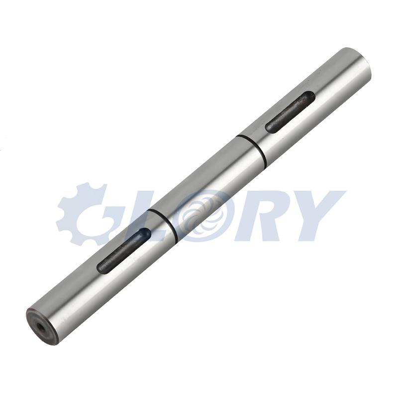
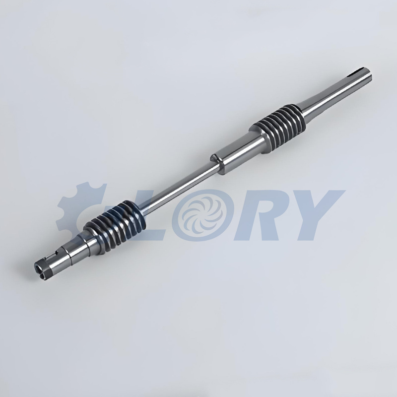
In the aerospace manufacturing industry, component precision is directly linked to flight safety. As core parts of engine hydraulic control systems, titanium alloy slender shafts impose exceptionally strict requirements on machining precision. An aerospace component enterprise once undertook a task to machine a batch of titanium alloy shafts with a length-diameter ratio of 15:1. These shafts featured specific parameters: 40mm in diameter, 600mm in length, and were made of TC4 titanium alloy. While this material boasts high strength and corrosion resistance, its thermal conductivity is merely one-fifth that of 45# steel. During machining, cutting heat accumulates easily, and its low elastic modulus makes it prone to permanent deformation under external forces.
In the initial machining stage, the enterprise adopted the traditional clamping method of “three-jaw chuck + single center”, with cutting parameters set as follows: spindle speed of 1200rpm, feed rate of 0.3mm/r, and cutting depth of 2mm. Ordinary cemented carbide inserts were used for machining. Post-machining inspection revealed that the radial runout of the shaft parts generally reached 0.12-0.15mm, far exceeding the design standard of within 0.05mm. More critically, obvious “drum-shaped” errors occurred within the 200mm range near the chuck end, while the tail end exhibited “tapered” deformation. Some parts were directly scrapped due to excessive runout, resulting in a qualification rate of less than 30%. After investigation by the technical team, the direct issues caused by excessive runout included uneven gaps with mating parts during assembly and unstable flow during hydraulic control—problems that completely failed to meet the service requirements of aerospace components.
To address this issue, the technical team implemented systematic process optimizations, ultimately stabilizing the runout within 0.02-0.03mm and increasing the qualification rate to 98%. The key improvement details merit in-depth analysis: In terms of the clamping system, the traditional single support was replaced with a “three-jaw chuck + dual center rests” combination. The first center rest was installed 150mm from the chuck, and the second 400mm from the first support point, forming a “three-point stable support” with the chuck. The distance between support points was strictly controlled at approximately 1/3 of the shaft length, effectively suppressing shaft bending deformation. For cutting parameters, combined with the machining characteristics of TC4 titanium alloy, the spindle speed was increased to 1800rpm—utilizing high-speed machining to reduce tool-workpiece contact time and heat accumulation—while the feed rate was reduced to 0.15mm/r and the cutting depth adjusted to 1.2mm. The parameter combination of “small cutting depth, medium speed, and low feed rate” avoided elastic deformation caused by large cutting forces. In terms of tool selection, CBN (cubic boron nitride) coated inserts were adopted. These inserts have a hardness exceeding HV3000 and a wear resistance 5-8 times that of ordinary cemented carbide. A major cutting edge angle of 91° was designed to minimize radial cutting forces, and a rake angle of -5° was set to enhance cutting edge strength, addressing the high hardness of titanium alloy. For process compensation, a “segmented cooling” strategy was specifically added: after machining every 50mm length, the process was paused for 2 minutes to force-cool the workpiece and tool with compressed air, controlling the workpiece surface temperature within 150°C to avoid cumulative thermal deformation.
II. Core Causes of Runout in Slender Shaft Machining
The runout issue in the aforementioned case is not an isolated incident but a common challenge in slender shaft machining. Combining machining principles and practical experience, the core causes can be categorized into three types, which interact with each other to exacerbate runout errors.
1. Insufficient Workpiece Rigidity: A Fundamental Physical Limitation
A slender shaft is defined as a shaft component with a length-diameter ratio exceeding 10:1. The titanium alloy shaft in the case, with a length-diameter ratio of 15:1, is a typical “flexible workpiece”. From the perspective of material mechanics, the rigidity of a shaft is proportional to the fourth power of its diameter and inversely proportional to the cube of its length—meaning slender shafts inherently have weak bending resistance. During machining, radial cutting forces, axial forces from the tool, and extrusion forces from chips all cause elastic deformation of the workpiece, shifting its axis away from the rotation center and resulting in runout. The “drum-shaped” bulge in the middle of the shaft during initial machining (due to the absence of center rest support) is a direct manifestation of insufficient rigidity.
2. Vibration Coupling Effect: A Hidden Hazard in Segmented Machining
Segmented turning is a common method for machining long shafts, but differences in clamping positions and cutting parameters between segments lead to the superposition of vibration frequencies, forming “vibration coupling”. During the initial machining in the case, the chuck clamping force was set to 0.25MPa without adjustment throughout the process. The large cutting forces in rough machining caused slight slippage between the chuck and workpiece, while the small cutting forces in finish machining failed to eliminate the positional deviation from this slippage. Additionally, the spindle speed was close to the natural frequency of the workpiece, triggering resonance and further amplifying runout errors. This vibration coupling not only causes radial runout but also leaves obvious vibration marks on the workpiece surface, impairing surface quality.
3. Cumulative Thermal Deformation: Precision Deviation Caused by Temperature
In metal cutting, over 80% of cutting heat is transferred to the workpiece and tool. For titanium alloy with poor thermal conductivity, thermal deformation is an even more prominent issue. During initial machining in the case, no effective cooling measures were adopted, and cutting heat raised the local temperature of the workpiece to over 300°C, causing axial and radial thermal expansion. Since both ends of the shaft were clamped, axial expansion was restricted and converted into radial bending deformation. This thermal deformation accumulated with prolonged machining, resulting in “tapered” errors at the tail end. Furthermore, increased tool wear from heat blunted the cutting edge, generating greater extrusion friction and forming a vicious cycle of “thermal deformation → increased cutting force → aggravated deformation”.
III. Systematic Solutions to Reduce Runout in Slender Shaft Machining
Resolving runout in slender shaft machining requires addressing the aforementioned causes by establishing a closed-loop control system from four dimensions—clamping system, cutting parameters, tool optimization, and process compensation—and formulating personalized solutions based on workpiece material and structural characteristics.
1. Clamping Method Optimization: Building a Rigid Foundation
The clamping system is the first line of defense against runout, guided by the core principles of “enhancing support, uniform force application, and releasing thermal deformation”.
The “dual centers + center rest” combination is the most widely used solution. Key implementation details include: using a dead center for positioning the initial segment to ensure datum precision; installing 1-2 follow-up center rests in the middle segment based on shaft length, with the distance between support points controlled at 1/3-1/2 of the shaft length. For example, the 600mm-long shaft in the case used a 400mm support spacing, avoiding excessive support density that hinders machining while preventing deformation from insufficient support; using a live center for the tail segment, leveraging its axial floating capability to reserve space for workpiece thermal expansion and avoid bending caused by thermal stress. For ultra-slender shafts with a length-diameter ratio exceeding 20:1, “segmented support with multiple center rests” is applicable, with a support point every 200-300mm.
Dynamic clamping force adjustment is a critical detail, requiring flexible adjustments based on machining stage and workpiece diameter: in rough machining, due to large cutting forces, the clamping force should be set to 0.15-0.2MPa to ensure no workpiece slippage; in finish machining, with smaller cutting forces, the clamping force is reduced to 0.08-0.12MPa to minimize elastic deformation caused by clamping. For thin-walled slender shafts, a “soft jaw + elastic expansion sleeve” combination is recommended. The soft jaw is turned to fit the workpiece outer circle, and the elastic expansion sleeve—driven hydraulically or pneumatically—distributes clamping force evenly across the workpiece surface, avoiding deformation from localized stress concentration.
2. Precise Control of Cutting Parameters: Balancing Efficiency and Precision
The selection of cutting parameters follows the principles of “matching material characteristics, gradient adjustment, and vibration suppression” to avoid runout caused by improper parameters.
Spindle speed must match material density and diameter: for ordinary steels like 45#, the recommended speed is 800-1200rpm for rough machining and 1500-2000rpm for finish machining; for difficult-to-machine materials such as titanium alloy and superalloy, the speed should be reduced to 600-1000rpm for rough machining and increased to 1500-1800rpm for finish machining. For instance, the 1800rpm finish machining speed used for the TC4 titanium alloy shaft in the case ensured machining efficiency while avoiding vibration from high-speed cutting. Additionally, calculations are required to avoid the natural frequency of the workpiece—generally, the speed is set to more than 1.2 times or less than 0.8 times the natural frequency to prevent resonance.
A “gradient reduction” strategy is adopted for feed rate and cutting depth: rough machining focuses on stock removal, with a feed rate of 0.3-0.5mm/r and cutting depth controlled at 5%-8% of the diameter; semi-finishing uses a feed rate of 0.2-0.3mm/r and cutting depth of 2%-3%; finish machining employs a feed rate of 0.1-0.2mm/r and cutting depth of 0.5%-1%. In the case, adjusting the feed rate from 0.3mm/r to 0.15mm/r and the cutting depth from 2mm to 1.2mm reduced the per-unit-time cutting load, minimizing workpiece force-induced deformation. Furthermore, “constant surface speed cutting” can be used in finish machining to maintain consistent cutting speed across all diameter segments of the workpiece, ensuring uniform machining precision.
3. Tool Geometric Parameter Optimization: Reducing Machining Interference
The geometric parameters of tools directly affect the magnitude and direction of cutting forces. Rational parameter design can effectively reduce radial forces and suppress runout.
The major cutting edge angle should be selected based on the machining stage: 75°-85° for rough machining to increase the proportion of axial cutting forces and enhance cutting edge strength for heavy stock removal; 90°-93° for finish machining to minimize radial cutting forces. For example, the 91° major cutting edge angle of the CBN insert in the case effectively reduced radial deformation of the workpiece. The rake angle is adjusted according to material hardness: positive rake angles (5°-10°) for soft materials to reduce cutting resistance; negative rake angles (-3° to -5°) for hard materials like titanium alloy to enhance cutting edge rigidity. The -5° rake angle design in the case was specifically tailored to the characteristics of TC4 titanium alloy.
Cutting edge honing and chip groove design should not be overlooked: a 0.03-0.05mm rounding honing on the tool rake face reduces cutting impact, prevents edge chipping, and extends tool life. Chip grooves adopt a “wide and shallow” design, with a groove width to cutting depth ratio of 1.5:1, ensuring smooth chip evacuation and avoiding vibration from chip entanglement on the workpiece. Additionally, tool coatings must match the material—CBN or AlTiN coatings are preferred for titanium alloy machining to reduce chemical adhesion between the tool and workpiece.
4. Process System Compensation: Eliminating Error Accumulation
Proactive compensation strategies can specifically eliminate runout errors caused by insufficient rigidity and thermal deformation, improving machining precision.
Reverse cutting is an effective method to address thermal deformation: 0.5-1mm of finish machining stock is reserved at both ends of the shaft, and a machining path from the middle to both ends is adopted to allow thermal expansion of the workpiece to dissipate toward the ends, avoiding bending deformation. For shafts with large length-diameter ratios, this can be combined with a “segmented machining + cooling” mode—such as pausing for 2 minutes after every 50mm of machining in the case—to minimize thermal deformation.
On-machine measurement and compensation achieve closed-loop precision control: laser alignment instruments or contact probes are installed on CNC lathes to monitor workpiece axis deviation in real-time. The CNC system automatically adjusts the Z-axis and X-axis coordinates, with the compensation amount controlled within 0.02-0.05mm. This method dynamically eliminates error accumulation during machining, making it particularly suitable for mass production.
Vibration dampers are used to suppress resonance: tuned mass dampers (TMD) are installed on the tool post or workpiece end. By adjusting the mass and stiffness of the damper, vibration energy is absorbed, reducing vibration amplitude by 40%-60%. For ultra-slender shafts, “follow-up dampers” can be used, moving synchronously with the tool to real-time suppress vibration in the machining area.
IV. Case Insights and Conclusions
The titanium alloy slender shaft machining case demonstrates that runout in slender shafts is not caused by a single factor but by the coupling of rigidity, vibration, thermal deformation, and other factors. Resolving this issue requires abandoning the “single adjustment” mindset and establishing a systematic “clamping-parameter-tool-compensation” solution, while formulating personalized strategies based on material characteristics and machining scenarios.
In practical production, additional details require attention: before machining, precision calibration of key components such as the spindle, centers, and center rests is necessary to ensure the datum error is within 0.005mm; trial cutting should be performed before mass production to optimize parameters based on inspection results; regular inspection of tool wear is required, with timely insert replacement to avoid error amplification from dull tools. Through the integrated application of these measures, the machining runout of slender shafts can be stably controlled within design requirements, achieving a balance between precision and efficiency.