

Key Points in Process Planning for Shaft Parts and Case Study Analysis
In mechanical manufacturing, the process planning for shaft parts is crucial for ensuring workpiece quality, improving production efficiency, and controlling costs. Rational process design effectively avoids machining errors, reduces procedural repetition, and ensures part precision and performance requirements. The key points of process planning are systematically explained below by combining general principles with a specific case.
I. General Principles of Process Design
-
Part Drawing Analysis and Technical Preparation
Before planning the process, a comprehensive analysis of the part drawing is essential to understand its structural characteristics, precision grade, material properties, and heat treatment requirements. Assembly drawings and acceptance standards should also be referenced to ensure the process design meets the overall assembly and functional needs. -
Typical Process Route: Using Carburized Parts as an Example
For carburized parts, the conventional process route is as follows:
Blank → Forging → Normalizing → Rough Machining → Semi-Finish Machining → Carburizing → Decarburization Machining → Quenching → Threading/Drilling/Milling Keyways → Rough Grinding → Low-Temperature Aging → Semi-Finish Grinding → Low-Temperature Aging → Finish Grinding -
Datum Selection Principles
-
Rough Datum: Priority is given to non-machined surfaces. If all surfaces require machining, the surface with the minimum machining allowance is selected as the datum, ensuring it is flat, firm, and avoiding uneven areas like gates. Rough datums are not reused.
-
Finish Datum: The principles of Datum Coincidence (using the design or assembly datum) and Datum Unification (using the same datum across multiple operations) should be followed. The finish datum should also coincide with the measurement datum whenever possible and be selected from stable, high-precision surfaces.
-
II. Case Study: Machining Process for an Internal Grinding Machine Spindle
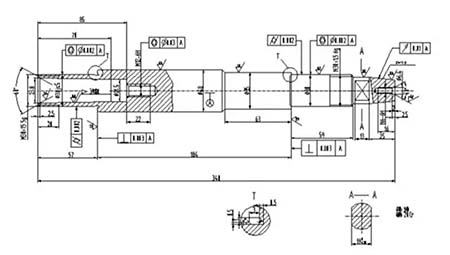
Taking a carburized spindle (Batch size: 40 pieces) made of 20Cr material as an example, its machining process is as follows:
Main Process Flow:
-
Turning (Complete Machining): Drill center holes, check taper contact area >60%, ensure runout of outer circles ≤0.1.
-
Heat Treatment: Carburizing and quenching to achieve surface hardness S0.9-C59.
-
Decarburization Machining: Perform operations like facing and repairing center holes on non-hardened areas (e.g., thread sections).
-
Semi-Finish Turning and Milling: Step-by-step turning of various outer diameters and relief grooves; milling keyway flats.
-
Heat Treatment and Datum Refinement: Quench to HRC59; lap center holes to Ra0.8.
-
Grinding Operations: Rough grind and semi-finish grind outer circles and tapers; internal grinding of taper hole (using V-block fixture for location).
-
Aging Treatment and Finish Machining: Perform low-temperature aging after rough grinding to relieve stress; finish grind outer circles and threads; final precision lapping of center holes to Ra0.4.
-
Cleaning and Rust Prevention: Clean, apply anti-rust oil, and store hanging vertically.
III. Explanation of Key Process Technologies
-
Establishment and Maintenance of the Datum System
-
Use center holes as the unified finish datum, conforming to the principles of datum coincidence and unification.
-
Apply the Mutual Datum Principle when machining the taper hole: first machine the taper hole using the outer circle for location, then precision machine the outer circle using the taper hole for location, gradually improving mutual positional accuracy.
-
Use Taper Plugs to maintain datum consistency. The taper plugs must be high-precision, stably installed, and include a thread for easy removal.
-
-
Special Treatment for Carburized Parts
-
Reserve a 2.5–3mm decarburization layer on areas not requiring hardening (e.g., threads), which is removed after carburizing and before quenching to ensure machinability.
-
A 3mm decarburization layer must also be reserved at the mouths of internal thread holes.
-
The total blank length is increased by 6mm to protect the center holes from being hardened.
-
-
Core Measures for Precision Control
-
Repeated Lapping of Center Holes: Center holes are lapped after heat treatment and before critical finish grinding steps. Their roundness and coaxiality directly affect the accuracy of outer circle grinding.
-
Multi-Stage Grinding and Stress Relief: Outer circle grinding is divided into rough, semi-finish, and finish stages. Low-temperature aging is scheduled after rough grinding to relieve grinding stresses.
-
High-Precision Positioning Fixtures: When finish grinding the Morse No. 3 taper hole, a V-block fixture locating on the two φ30js5 outer circles is used to guarantee geometric tolerances and a contact area greater than 80%.
-
IV. Summary
The process design for shaft parts is a systematic project that requires comprehensive consideration of material properties, heat treatment distortion, datum transfer, and precision evolution. The spindle case study described here, through rational datum selection, strict carburizing control, precise stress relief, and multi-stage grinding, achieved the manufacturing goals of high precision and high reliability, providing a typical example for the process planning of similar parts.